To make the most of your Raspberry Pi, it’s essential to understand its GPIO (General Purpose Input Output) pins. These tiny but powerful pins are like the heart and soul of the Raspberry Pi, allowing it to interact with the outside world and bring your projects to life.
Whether you’re into robotics, gaming, or simply exploring electronics, GPIO pins are your go-to tools for endless possibilities.
But what exactly can you do with these GPIO pins? Well, the answer is quite a lot actually! You can connect various components like sensors, motors, LEDs, and displays directly to the GPIO pins. This direct connection allows you to control and communicate with these components using programming languages like Python and JavaScript.
In this comprehensive Raspberry Pi Pinout guide, we’ll not only learn about the role and importance of GPIO pins, but we’ll also explore the functionalities of these pins and how they can be used to build cool projects. Additionally, we’ll dive into the difference between physical pin numbering and BCM pin numbering, and why using BCM pin numbering is highly recommended for consistency and compatibility.
So, whether you’re a tech enthusiast, a hobbyist, or a student eager to explore the world of electronics and programming, join us on this GPIO adventure with your Raspberry Pi. Let’s unleash the full potential of these magical pins and ignite our creativity to embark on exciting projects together!
Understanding GPIO Pins And The Raspberry Pi Pinout
GPIO pins on the Raspberry Pi are digital and can be in either an off or on state. They can be programmed to receive or send current, making them highly versatile. Common programming languages like Python, JavaScript, and node-RED can be used to control the state and direction of these pins.
The GPIO pins operate at 3.3v and have a maximum current draw of 16mA. While they can power one or two LEDs with a resistor, components requiring higher current, such as DC motors, necessitate aditional external components to protect the GPIO from damage.
YOU MIGHT LIKE: Can You Mine Crypto On A Raspberry Pi?
How Many GPIO Pins Does A Raspberry Pi Have?
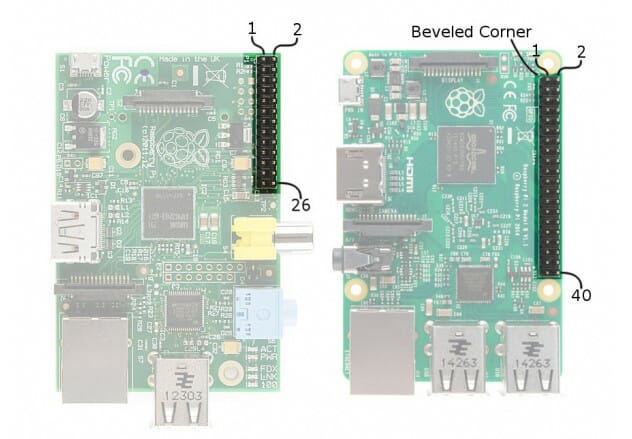
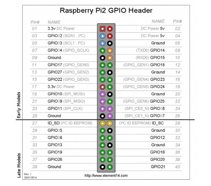
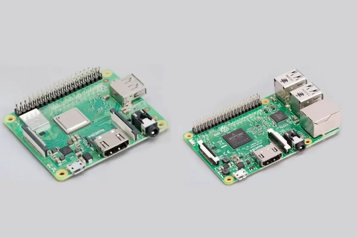
One important thing to know is that the number of GPIO pins has changed over the years. All Raspberry Pi models released after 2014, such as the Raspberry Pi 3, 4, and newer versions, come equipped with 40 GPIO pins. On the other hand, earlier models, like the Raspberry Pi Model B, B+, and those released before 2014, had 26 GPIO pins
How To Reference GPIO Pins
There are multiple ways to reference GPIO pins. Physical pin numbering, which follows an odd or even number sequence, is based on their physical location. On the other hand, Broadcom (BCM) pin numbering, the officially supported scheme, directly connects the pins to the Raspberry Pi’s System on a Chip (SoC). Understanding and using the BCM pin numbering scheme is recommended.
BCM Pin Numbering
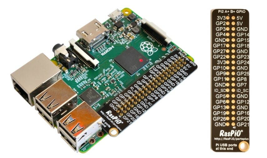
BCM (Broadcom) pin numbering is the officially supported and widely used scheme for referring to the GPIO pins on the Raspberry Pi. It is based on the direct connections between the pins and the Broadcom System on a Chip (SoC) at the heart of the Raspberry Pi.
Unlike physical pin numbering, which follows a sequential arrangement based on the physical location of the pins on the GPIO header, BCM pin numbering might seem chaotic at first glance. However, understanding this scheme is essential as it provides a consistent and logical way to interact with the Raspberry Pi’s GPIO.
In the BCM pin numbering system, each GPIO pin is assigned a unique number that corresponds to the Broadcom SoC’s internal mapping. This direct link to the processor allows for efficient communication with various sensors, components, and add-ons, making it an ideal choice for programming and projects.
To illustrate, let’s consider an example. GPIO17 in physical pin numbering is located at pin 11 on the GPIO header, while in BCM pin numbering, it is referred to as BCM17. Similarly, GPIO22 and GPIO27 correspond to BCM22 and BCM27, respectively.
Using BCM pin numbering is highly recommended in tutorials and projects since it is the officially supported scheme by the Raspberry Pi Foundation. This consistency ensures compatibility across different projects and resources, streamlining the learning process for both beginners and experienced developers.
YOU MIGHT LIKE: How To Run Steam On A Raspberry Pi
GPIO Pin Layout
To understand the pin layout, let’s start from the top left, closest to the micro SD card slot. Physical pin 1 provides 3v3 power, and pin 2 provides 5v power. Moving down each column, pin numbers increase in an odd number sequence for the first column and an even number sequence for the second column. However, many tutorials use the BCM pin numbering scheme for consistency and compatibility.
I2C, SPI, and UART Interfaces
Certain GPIO pins also have alternate functions to support I2C, SPI, and UART protocols. These interfaces enable communication with different devices. For example, GPIO3 and GPIO4 can serve as SDA and SCL pins for I2C connections. Enabling these interfaces through the Raspberry Pi Configuration application expands the Pi’s capabilities.
I2C – Inter-Integrated Circuit
I2C is a low-speed two-wire serial protocol that connects devices using a master-slave relationship. Each slave device requires a unique address obtained from the manufacturer. With SDA and SCL connections, I2C allows for easy integration of various components like LCD/OLED screens and temperature sensors. While it may seem trickier to grasp than standard GPIO pins, learning I2C opens doors to using higher precision sensors.
SPI – Serial Peripheral Interface
SPI is another protocol for connecting devices to the Raspberry Pi. It employs a master-slave relationship and is often used for short-distance data transmission between microcontrollers and components like shift registers and sensors. MOSI (Master Out Slave In) and MISO (Master In Slave Out) pins facilitate data exchange, synchronized by a clock signal (SCLK).
UART – Universal Asynchronous Receiver/Transmitter
UART, also known as “Serial,” provides a console/terminal login for headless setups. It allows you to connect to the Pi without a keyboard or pointing device. While headless setups are typically achieved over a network or direct USB connection, UART provides a reliable alternative when network access is not available. The Transmit (GPIO14) and Receive (GPIO15) pins are used for UART communication.
Ground (GND)
Ground connections are crucial for completing electrical circuits and measuring voltages. The Raspberry Pi has multiple GND pins, and their selection depends on personal preference or convenience when connecting components.
Power Pins
The 5v pins provide direct access to the 5v power supply from the mains adapter. Care must be taken when using these pins directly, as they bypass safety features like voltage regulators and fuses. The 3v pin supplies a stable 3.3v for components and LED testing.
Conclusion
Understanding the Raspberry Pi GPIO pins is essential for building exciting projects. By grasping the functionalities, pin layouts, and alternate interfaces, you can harness the full potential of your Raspberry Pi. Whether you’re a beginner or an experienced developer, exploring the capabilities of GPIO pins opens up a world of creative possibilities.
Remember to refer to the official Raspberry Pi documentation and consult product specifications to ensure proper pin usage for your specific projects. Start experimenting and enjoy the journey of building with Raspberry Pi GPIO pins!
READ NEXT: How To Create a Raspberry Pi Airplay Receiver
Frequently Asked Questions
What are GPIO pins on Raspberry Pi?
GPIO pins on the Raspberry Pi are digital pins that allow the Pi to interact with external components. They can be programmed to send or receive current, enabling a wide range of projects.
How can I control GPIO pins on Raspberry Pi?
You can control GPIO pins on the Raspberry Pi using programming languages like Python, JavaScript, or node-RED. Popular libraries such as RPi.GPIO and GPIO Zero provide interfaces to easily control GPIO pins.
Do I need to be careful when using GPIO pins?
When working with GPIO pins, consider the operating voltage and current limits. For higher-current devices, use external components like resistors to protect the pins. It is important to refer to official documentation and follow best practices to prevent damage to your Raspberry Pi.
- How To Uninstall Packages On Ubuntu - March 13, 2024
- How To Restart Ubuntu Using The Terminal - March 13, 2024
- What Is The Steam Deck | Experience Modern Handheld Gaming - March 12, 2024



![How To Host A Website On A Raspberry Pi: A Step By Step Guide How To Host Your Own Website On Raspberry Pi [Ultimate Guide]](https://raspians.com/wp-content/uploads/2023/02/How-To-Host-Your-Own-Website-On-Raspberry-Pi-Ultimate-Guide-1-150x150.jpg)
